


News


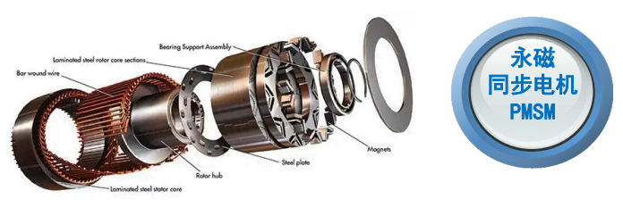


The Core of Permanent Magnet Motors: A Complete Analysis of the Pros and Cons of Four Major PM Rotor Topologies – How to Correctly "Arrange Your Troops"
Choose the right topology, and performance doubles; choose the wrong one, and you get half the result with twice the effort.
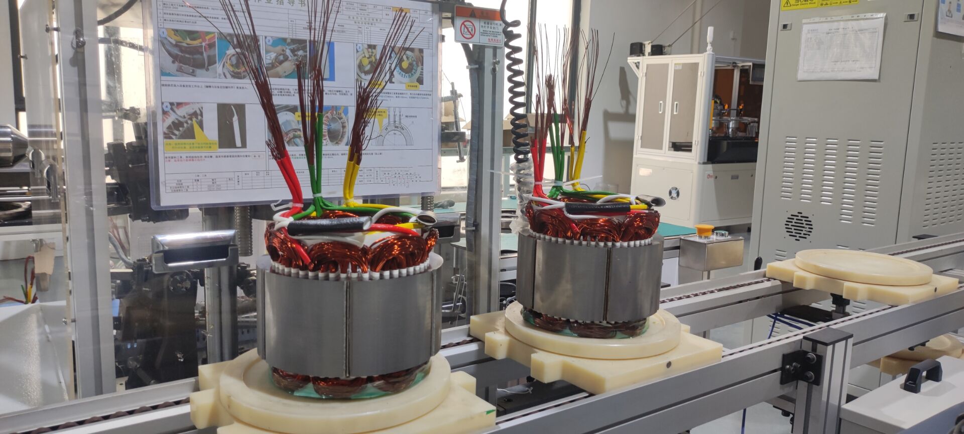
Inside the core of a permanent magnet (PM) motor – the rotor – the arrangement of the magnets is never random. It is like a precise military formation, directly determining the motor's combat effectiveness: torque, efficiency, speed, cost, and even reliability.
Different topologies represent the wisdom of engineers seeking the optimal balance between five core objectives: high flux density, flux-weakening capability, cost control, manufacturability, and torque smoothness.
This article provides an in-depth, easy-to-understand analysis of the four mainstream PM rotor topologies, helping you fully grasp their structural characteristics, unique advantages, inherent disadvantages, and typical applications, offering a clear "layout map" for your motor design or selection.
Part 1: Design Objectives – The Five Core Trade-offs in PM Layout
Before choosing a specific topology, the optimization goals must be clear. All layout designs revolve around resolving the following core contradictions:
-
High Magnetic Flux Density: To generate a stronger magnetic field within the same volume, directly increasing the motor's torque and power density, making it more powerful and compact.
-
Flux-Weakening & Speed Range Extension: When the motor runs at high speed, the magnetic field must be actively weakened to prevent overvoltage. A good layout can broaden the constant power operating range, allowing the motor to run faster and more stably.
-
Cost Control: Under the premise of meeting performance requirements, minimizing the use of expensive rare-earth permanent magnet materials is key to product competitiveness.
-
Manufacturability & Reliability: Is the structure easy to manufacture and assemble? Can it withstand the tremendous centrifugal force under high-speed rotation? This relates to mass production feasibility and lifespan.
-
Torque Smoothness: An excellent topology can effectively suppress torque ripple, making motor operation smoother and quieter, enhancing the experience in high-end applications.
Part 2: In-Depth Comparison of Four Mainstream PM Rotor Topologies
Surface-Mounted / Radial Topology: The Economical "All-Rounder"
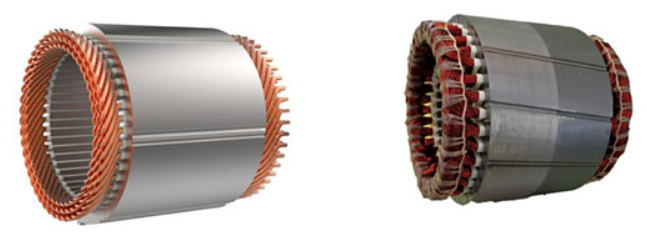
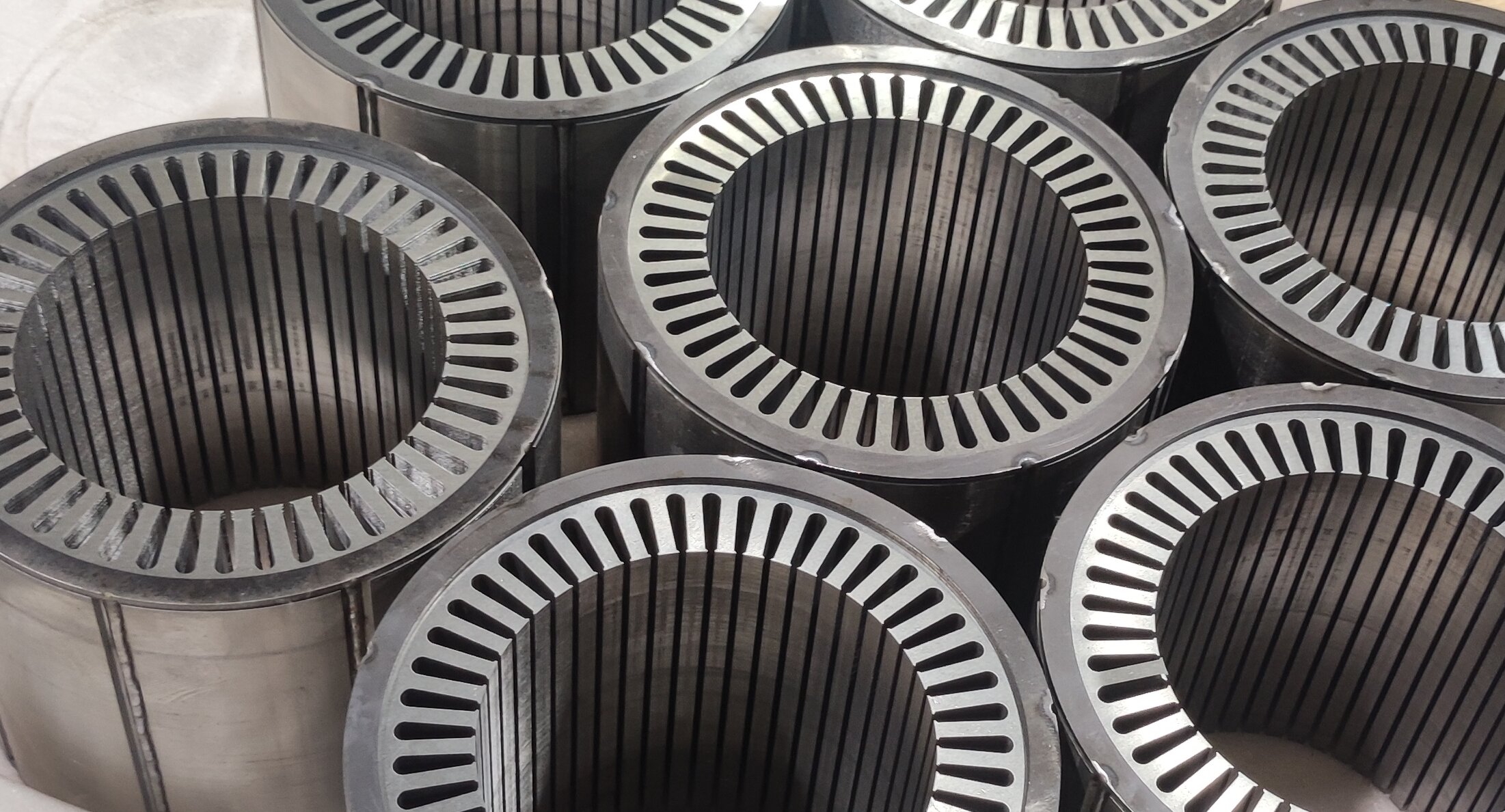
This is the most common and classic topology. The permanent magnets are attached or embedded on the surface of the rotor core like tiles, with their magnetization direction along the radial direction.
Key Advantages:
-
Simple Structure: Easiest to manufacture and assemble, resulting in lower cost.
-
Low Rotor Inertia: The rotor is lightweight, suitable for applications requiring fast start-stop and high dynamic response.
-
Excellent Flux-Weakening Capability: The air-gap magnetic field is easily regulated by the armature reaction, offering superior high-speed performance.
Inherent Disadvantages:
-
Relatively Low Torque Density: The magnetic flux path is direct, with a small reluctance torque component.
-
Demagnetization Risk: The magnets are directly exposed to the armature reaction field, posing a risk of demagnetization under extreme conditions like short circuits.
-
Reinforcement Needed for High Speed: Surface-mounted magnets often require an additional retaining sleeve (e.g., carbon fiber banding), adding complexity and cost.
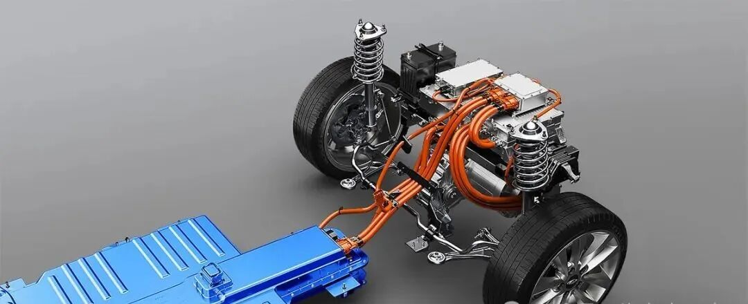
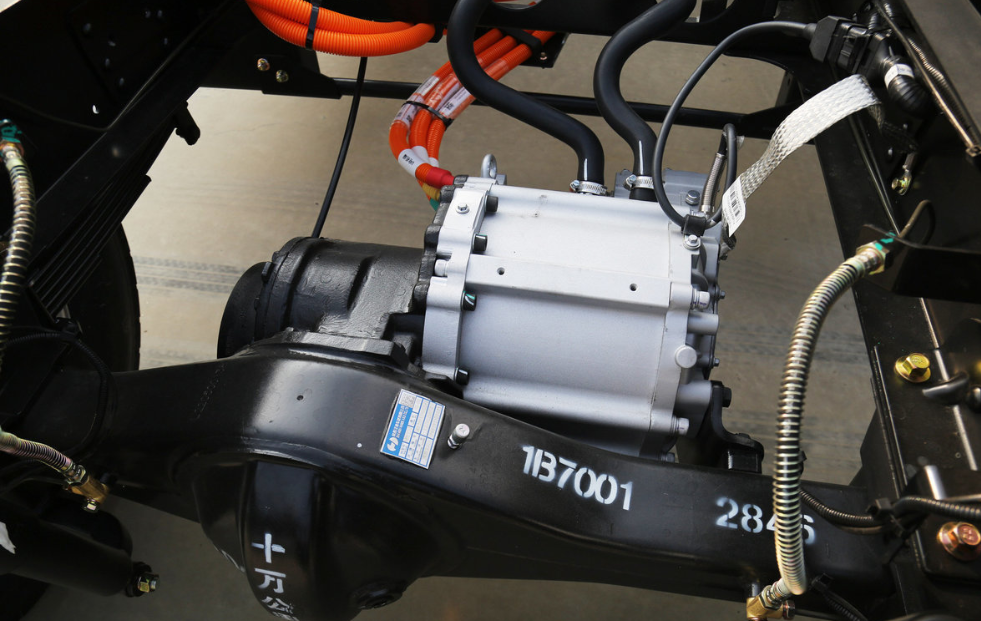
Typical Application Scenarios: Cost-sensitive applications requiring a wide speed range. Examples: Home appliance motors, standard industrial servo motors, early-generation electric vehicle traction motors.
Interior Buried / Tangential Topology: The "Powerhouse" for Density
The permanent magnets are embedded inside the rotor core, with their magnetization direction tangential. Adjacent magnets have opposite polarities, creating a "flux focusing" effect where their fluxes combine for one magnetic pole.
Key Advantages:
-
Flux Focusing Effect: Significantly increases the air-gap flux density, leading to higher torque and power density.
-
Saves PM Material: Can reduce the amount of expensive materials like NdFeB for equivalent performance.
-
Good Mechanical Strength: The magnets are protected by the rotor iron, naturally suitable for high-speed operation without the need for an additional sleeve.
Inherent Disadvantages:
-
More Complex Structure: Requires complex magnet slots and "flux barriers" or bridges, resulting in higher manufacturing process requirements.
-
Poorer Flux-Weakening Capability: The magnetic path has low reluctance, making it more susceptible to armature reaction demagnetization, resulting in slightly weaker high-speed range extension.
-
Leakage Flux Management Challenge: Requires careful design to control internal magnetic flux leakage.
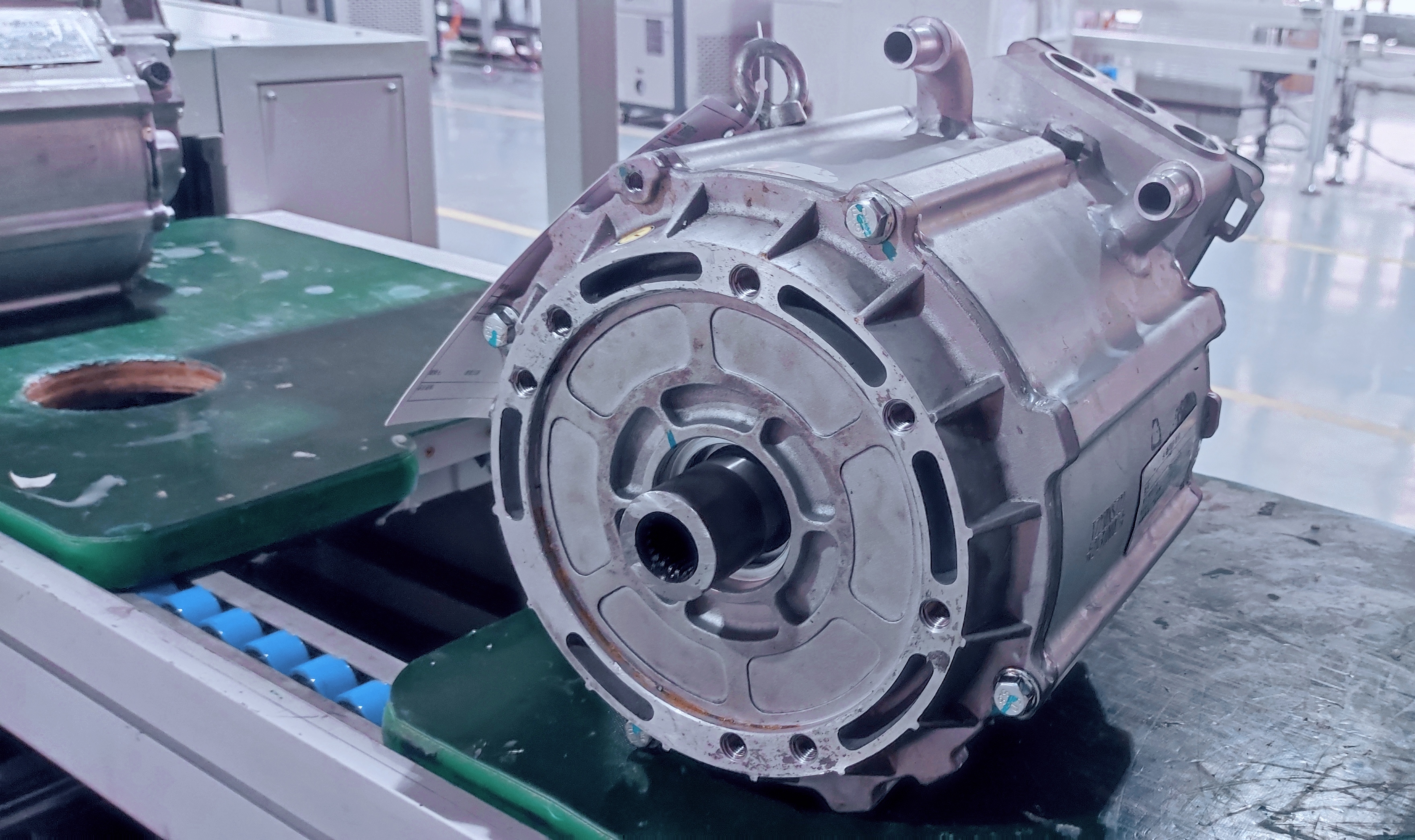
Typical Application Scenarios: Applications pursuing high power/torque density at medium to high speeds. Examples: Modern electric vehicle traction motors, aerospace actuators, high-performance servo drives.
V-Shaped / Spoke-Type / Hybrid Topology: The "All-Around Champion"
Typically arranged in a "V-shape" or "U-shape", this topology cleverly combines the advantages of radial and tangential magnetic circuits, utilizing both radial and tangential magnetization components.
Key Advantages:
-
Peak Power Density: The preferred choice for today's high-performance PM synchronous motors, achieving optimal flux utilization and torque output.
-
High Reluctance Torque Utilization: Exhibits a significant saliency ratio, making full use of reluctance torque to improve overall efficiency and power density.
-
Large Design Freedom: Parameters like the "V-angle" and magnet thickness provide broad space for performance optimization.
Inherent Disadvantages:
-
Most Complex Structure: The rotor lamination die is complex, and magnet installation is extremely challenging, leading to the highest manufacturing cost.
-
Highly Process-Dependent: Requires extremely high precision in production equipment and process control.
Typical Application Scenarios: Flagship areas with extreme performance demands. Examples: High-end electric vehicles, luxury hybrid vehicles, high-end industrial robots, precision CNC machine tool spindles.
Halbach Array: The "Sci-Fi Weapon" in Exploration
A special magnet arrangement theory. By combining magnet blocks with different magnetization directions in a specific sequence, the magnetic field is significantly enhanced on one side (air-gap side) of the array and nearly canceled on the other.
Key Advantages:
-
Theoretical Limit of Air-gap Flux Density: Can produce a much stronger magnetic field on the air-gap side compared to traditional topologies, representing the "ultimate" direction for increasing torque density.
-
Excellent Field Waveform: Can produce a nearly ideal sinusoidal magnetic field, greatly reducing torque ripple and core losses, resulting in extremely smooth, quiet, and efficient operation.
-
Low Back-side Leakage: The magnetic field is highly concentrated on the air-gap side, with minimal flux in the back of the rotor core, allowing for thinner core backs or reduced losses.
Inherent Disadvantages:
-
Extremely Difficult Design & Manufacturing: Requires precise assembly of magnets with various shapes and magnetization directions. Magnetization and assembly processes are major bottlenecks, making costs prohibitively high.
-
Not Yet Mass-Commercialized: Primarily limited by cost and process, not a mainstream industrial choice.
Typical Application Scenarios: Cutting-edge fields with extreme demands on weight, volume, and performance. Examples: High-precision voice coil actuators, particle accelerators, magnetic levitation systems, special-purpose drone motors.
Part 3: Summary
|
Topology Type |
Core Advantages |
Main Disadvantages |
Application Scenarios |
|---|---|---|---|
|
Surface-Mounted (Radial) |
Simple structure, low cost, excellent flux-weakening, fast dynamic response |
Lower torque density, demagnetization risk, needs reinforcement for high speed |
Cost-sensitive, wide-speed general-purpose applications |
|
Interior Buried (Tangential) |
High torque density, material-saving, good mechanical strength |
More complex structure, slightly poorer flux-weakening |
Performance applications pursuing high density at medium-high speeds |
|
V-Shaped / Hybrid |
Extremely high power density, optimal overall performance, large design space |
Most complex structure, difficult process, highest cost |
High-end/flagship fields pursuing ultimate performance |
|
Halbach Array |
Theoretical limit for air-gap flux density, excellent waveform, low losses |
Extremely difficult design/manufacturing, very high cost |
Specialized, cutting-edge technology fields |
There is no absolute best in the "battle formation" of permanent magnet motors, only the most suitable balance for a specific application.
Choosing Surface-Mounted, you gain economy and high-speed capability; choosing Interior Buried, you strike a balance between performance and cost; choosing V-Shaped/Hybrid, you reach the peak of performance for mass-produced motors; and exploring the Halbach Array is about challenging the theoretical limits of the next generation of motors.
Understanding the underlying logic and trade-offs of these four topologies is the first step to correctly designing, selecting, and using permanent magnet motors, and it is the key to unleashing a motor's full potential.